 |
eFEX firmware
1.7.3
ATLAS l1-calo - electron and tau feature extraction firmware for eFEX boards
|
Back to eFEX documentation
|
eFEX firmware
1.7.3
ATLAS l1-calo - electron and tau feature extraction firmware for eFEX boards
|
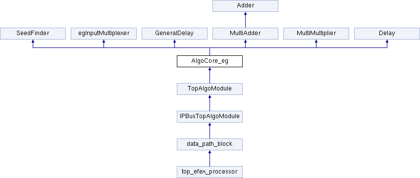
Core of the electromagnetic algorithm. More...
Entities | |
| Behavioral | architecture |
| Core of the electromagnetic algorithm. More... | |
Libraries | |
| IEEE | |
| infrastructure_lib | |
Use Clauses | |
| STD_LOGIC_1164 | |
| NUMERIC_STD | |
| DataTypes | Package <DataTypes> |
Generics | |
| EG_ALGO_VERSION | std_logic_vector ( 1 downto 0 ) |
Ports | ||
| CLK200 | in | std_logic |
| IN_ParWs | in | AlgoParameters ( 2 downto 0 ) |
| IN_ParREta | in | AlgoParameters ( 2 downto 0 ) |
| IN_ParHadron | in | AlgoParameters ( 2 downto 0 ) |
| IN_glob_Position | in | AlgoRegister := ( others = > ' 0 ' ) |
| IN_ParDeadMat_b0 | in | AlgoParameter |
| enable bit mask for material correction | ||
| IN_ParDeadMat_b1 | in | AlgoParameter |
| IN_ParDeadMat_b2 | in | AlgoParameter |
| IN_ParDeadMat_b3 | in | AlgoParameter |
| IN_Energy_threshold | in | DataWord |
| IN_Cond_threshold | in | DataWord |
| IN_Data | in | TriggerTowers ( 8 downto 0 ) |
| OUT_TOB | out | TriggerObject_eg |
Core of the electromagnetic algorithm.
The total latency of this block is 10 clock cycles, this is a table representing the timing:
| clock cycle | 0 | 1 | 2 | 3 | 4 | 5 | 6 | 7 | 8 | 9 | 10 |
|---|---|---|---|---|---|---|---|---|---|---|---|
| RAM address | 0 | 1 | 2 | 3 | 4 | 0 | 1 | 2 | 3 | 4 | 0 |
| seed finder | X | X | |||||||||
| In mux | X | X | |||||||||
| Adders env | X | X | X | X | |||||||
| Addders core | X | X | X | X | X | X | X | ||||
| Multipliers | X | X | X | ||||||||
| Seed delay | X | X | X | X | X | X | X | X | X | ||
| TOB energy | X | X | |||||||||
| Threshold delay | X | X | X | ||||||||
| Conditions | X | X | |||||||||
| Dead Mat. Corr. | X | ||||||||||
| DMC delay | X | X |
At clock cycle 0 the data is provided to the algorithm.
At clock cycle 1, the seed is ready and so is the data coming out of the input multiplexer, which is provided to the adders.
At clock cycle 5, the envoronment sums are ready and fed into the multipliers.
At clock cycle 8, all the sums and the multiplications are done and the valued are fed into the conditions
At clock cycle 8 also the energy threshold is applied.
At clock cycle 10 the TOBs are formed with the conditions bits and the Energy
The parameters used to evaluate the conditions are read from the RAM at clock cycle 0 or 5 (the RAM address goes form 0 to 4).
A delay of 2 clock cycles is used to pipeline the correct value for Dead Materal Correction (DMC) parameters that are read at clock cycle 2, i.e. when data is provided to the adders.
A delay of 3 clock cycles is used to delay the energy thresholds which are read at clock cycle 8, i.e. when the conditions are evaluated.
Definition at line 49 of file AlgoCore_eg.vhd.
 1.9.1
1.9.1