 |
eFEX firmware
1.7.3
ATLAS l1-calo - electron and tau feature extraction firmware for eFEX boards
|
Back to eFEX documentation
|
eFEX firmware
1.7.3
ATLAS l1-calo - electron and tau feature extraction firmware for eFEX boards
|
RAW Calorimeter Data Readout Logic for process FPGA. More...
Entities | |
| RTL | architecture |
| RAW Calorimeter Data Readout Logic for process FPGA. More... | |
Libraries | |
| ieee | |
| ipbus_lib | |
| UNISIM | |
| UNIMACRO | |
| TOB_rdout_lib | |
Use Clauses | |
| std_logic_1164 | |
| numeric_std | |
| ipbus | |
| vcomponents | |
| data_type_pkg | Package <data_type_pkg> |
| TOB_rdout_ip_pkg | Package <TOB_rdout_ip_pkg> |
Generics | |
| FPGA_NUMBER | integer := 1 |
| Integer used to distinguish different FPGAs having a slightly different firmware. | |
Ports | ||
| RST | in | std_logic |
| hw_addr | in | std_logic_vector ( 1 downto 0 ) |
| FPGA Hardware Address. | ||
| RST_spy_mem_wr_addr | in | std_logic |
| RST_spy_mem_wr_addr, counter reset Pulse by software command. | ||
| RAW_FIFO_sw_rst | in | std_logic |
| RAW Readout FIFO reset Pulse by software command. | ||
| RAW_data_in | in | RAW_data_227_type |
| Calorimeter data array 49 x 227b input frames. | ||
| clk_40M_rdout | in | std_logic |
| 40Mhz input signal used only for RAW data readout | ||
| clk_280M_in | in | std_logic |
| 280Mhz input signal | ||
| clk_load_in | in | std_logic |
| 40Mhz input signal at 20% duty cycle | ||
| ipb_clk | in | std_logic |
| ipb_clk signal is input from master to slaves | ||
| RAW_ready_in | in | std_logic |
| Ready signal from control FPGA to receive RAW calorimeter data. | ||
| RAW_TXOUTCLK | in | std_logic |
| Calorimeter TXOUTCLK to read Calorimeter data to MGT for transmission to control FPGA. | ||
| L1A_in | in | std_logic |
| L1A input signal. | ||
| BCN_ID_in | in | std_logic_vector ( 11 downto 0 ) |
| Bunch Crossing ID 12 bits. | ||
| L1A_ID_in | in | std_logic_vector ( 31 downto 0 ) |
| 8b Extended L1A ID & 24b LIA_ID of the L1A Counter | ||
| raw_rd_all_in | in | std_logic |
| readout all raw data links, when set all RAW data from 49 fibres are readout | ||
| pre_ld_wr_addr | in | std_logic_vector ( 9 downto 0 ) |
| latency pre-load for DPRAM write address | ||
| RAW_FIFO_FULL_THRESH_ASSERT | in | std_logic_vector ( 8 downto 0 ) |
| RAW FIFO full flag assert threshold. | ||
| RAW_FIFO_FULL_THRESH_NEGATE | in | std_logic_vector ( 8 downto 0 ) |
| RAW FIFO full flag negate threshold. | ||
| RAW_FIFO_data_count | out | std_logic_vector ( 8 downto 0 ) |
| RAW FIFO occupancy data count. | ||
| raw_busy_thresh_assert | in | STD_LOGIC_VECTOR ( 8 downto 0 ) |
| raw BUSY flag threshold assert | ||
| raw_busy_thresh_negate | in | STD_LOGIC_VECTOR ( 8 downto 0 ) |
| raw BUSY flag threshold de-assert | ||
| cntr_load_en | in | std_logic |
| latency pre-load enable signal for DRPAM write address | ||
| RAW_data_FIFO_flags | out | std_logic_vector ( 31 downto 0 ) |
| RAW data block FIFO flags. | ||
| RAW_out_to_MGT_is_char | out | std_logic |
| calorimeter data is CHAR signal to MGT & Control FPGA | ||
| RAW_data_out | out | std_logic_vector ( 31 downto 0 ) |
| calorimeter 32b data output to MGT & Control FPGA | ||
| mgt_enable_in | in | STD_LOGIC_VECTOR ( 48 downto 0 ) |
| MGT enable signals - use to enable/disable readout on error. | ||
| frame_count | out | std_logic_vector ( 31 downto 0 ) |
| numer of frames in the link output FIFO to be transmitted to MGT & Control FPGA | ||
| read_on_err_out | out | STD_LOGIC |
| Read RAW data on error flag. | ||
| TTC_read_all_in | in | std_logic |
| Privilege Read signal input. | ||
| RAW_FIFO_pFULL_THRESH_ASSERT | in | std_logic_vector ( 8 downto 0 ) |
| Derandomisation FIFO partial full flag assert threshold. | ||
| RAW_FIFO_pFULL_THRESH_NEGATE | in | std_logic_vector ( 8 downto 0 ) |
| 36b derandomisation FIFO partial full flag negate threshold | ||
| BCN_FIFO_pFULL_THRESH_assert | in | std_logic_vector ( 8 downto 0 ) |
| BCN FIFO partial full flag assert threshold. | ||
| BCN_FIFO_pFULL_THRESH_negate | in | std_logic_vector ( 8 downto 0 ) |
| BCN FIFO partial full flag negate threshold. | ||
| BCN_FIFO_RAW_rd_data_count | out | STD_LOGIC_VECTOR ( 8 downto 0 ) |
| BCN & L1A FIFO occupancy for RAW Readout. | ||
| Link_output_FIFO_RAW_pfull_thresh_assert | in | std_logic_vector ( 12 downto 0 ) |
| Link output FIFO (before MGT) partial full flag assert threshold. | ||
| Link_output_FIFO_RAW_pfull_thresh_negate | in | std_logic_vector ( 12 downto 0 ) |
| Link output FIFO (before MGT) partial full flag negate threshold. | ||
| Link_output_FIFO_RAW_rd_data_count | out | std_logic_vector ( 12 downto 0 ) |
| Link output FIFO (before MGT) occupancy data count. | ||
| SPY_mem_wr_addr | out | std_logic_vector ( 10 downto 0 ) |
| RAW Data SPY Memory write address register (read only) | ||
| ipbus_out_raw_dpram | out | ipb_rbus |
| IPBus signal coming from RAW SPY DPRAM. | ||
| ipbus_in_raw_dpram | in | ipb_wbus |
| IPBus signal going to RAW SPY DPRAM. | ||
| link_error_flags | out | std_logic_vector ( 53 downto 0 ) |
| 54-b error flags from the Error Flag FIFO to IPBUS register | ||
| busy_raw | out | std_logic |
| raw data busy out to control FPGA | ||
| raw_fsm_monitor | out | std_logic_vector ( 31 downto 0 ) |
| Monitor RAW Readout state machines. | ||
RAW Calorimeter Data Readout Logic for process FPGA.
This module received synchronised 224-b Calorimeter RAW data and its associated 3-b error flags, and produces writes the data as 7 x 32-b words into dual port scrolling memory.
Upon receiving L1A signals, it produces RAW events of 32-b words with Headr, Trailer and error flags for transmission to control FPGA.
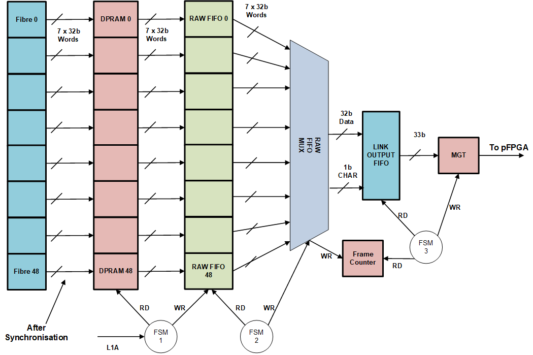
There are 40 ECAL and 9 HCAL input fibres.
Different RAW event are generated depending on buffer levels and control settings:
Sequence of Buffers occupancy levels:
Under Safe Mode operation if the occupancy of TTC FIFO or Link Output FIFO, reaches its FULL occupancy level, then the system synchronisation is lost.
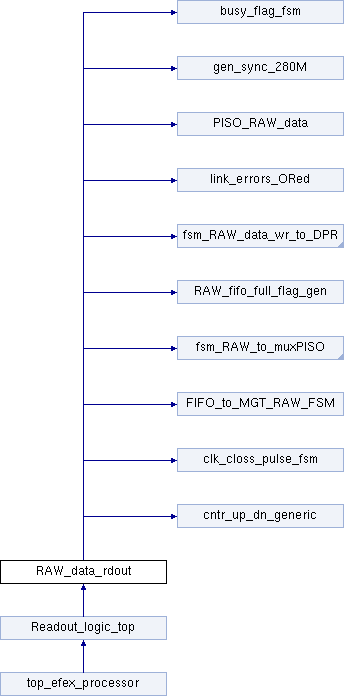
The GEN_CHANNEL loop, generates 49 copies of the RAW data readout blocks within it,these are:
The output of RAW Readout is: 32-bit data word 1-bit data is CHAR 1-bit valid which is the write enable to Link Output FIFO
Header Word:
Header Word 2:
Fibre Trailer Word:
Trailer Word 1:
Trailer Word 2:
Trailer Word 3:
CHAR constants are defined in data_type_pkg.vhd for reference only
Definition at line 118 of file RAW_data_rdout.vhd.
 1.9.1
1.9.1