 |
eFEX firmware
1.7.3
ATLAS l1-calo - electron and tau feature extraction firmware for eFEX boards
|
Back to eFEX documentation
|
eFEX firmware
1.7.3
ATLAS l1-calo - electron and tau feature extraction firmware for eFEX boards
|
RAW Calorimeter Data Readout Logic for process FPGA. More...
Processes | |
| U0_clk | ( clk_in_280M_i ) |
| proc1 | ( clk_40M_rdout ) |
| U5_1_clk | ( clk_in_280M_i ) |
| U5c_1_clk | ( clk_in_280M_i ) |
| U11_clk_proc | ( RAW_TXOUTCLK ) |
| U14_stop_wr | ( RAW_TXOUTCLK ) |
Constants | |
| chan_no | integer := 49 |
| number of input fibres | |
Types | |
| DPRAM_addr_1b_type | ( ( chan_no - 1 ) downto 0 ) std_logic_vector ( 0 downto 0 ) |
| RAW_fifo_d_count_type | ( ( chan_no - 1 ) downto 0 ) std_logic_vector ( 8 downto 0 ) |
Signals | |
| DPR_rd_addr_i | std_logic_vector ( 9 downto 0 ) |
| DPR_wr_addr_i | std_logic_vector ( 9 downto 0 ) |
| DPR_rd_addr_i_1dly | std_logic_vector ( 9 downto 0 ) |
| DPR_wr_addr_i_1dly | std_logic_vector ( 9 downto 0 ) |
| FIFO_RAW_Data_dout_i | DPR_RAW_out_36_type |
| FIFO_RAW_Data_dout_i_1dly | DPR_RAW_out_36_type |
| link_error_flags_tmp | link_error_type |
| link_err_4b_in_i | std_logic_vector ( 3 downto 0 ) |
| channel_error_49b_i | std_logic_vector ( 48 downto 0 ) |
| link_error_flags_54b_i | std_logic_vector ( 53 downto 0 ) |
| FIFO_error_flags_54b_i | std_logic_vector ( 53 downto 0 ) |
| req_err_rd_raw_i | std_logic := ' 0 ' |
| FIFO_error_flags_valid_i | std_logic |
| PISO_data_out_i | DPR_RAW_out_36_type |
| DPR_RAW_out_i | DPR_RAW_out_36_type |
| DPR_RAW_out_i_1dly | DPR_RAW_out_36_type |
| RST_i | std_logic |
| Read_all_i | std_logic |
| RAW_FIFO_sw_rst_i | std_logic |
| clk_in_280M_i | std_logic |
| PISO_sync_out_i | t_49_arr_1b |
| PISO_data_out_valid_i | t_49_arr_1b |
| L1A_in_i | std_logic |
| L1A_in_1dly | std_logic |
| L1A_in_a | std_logic |
| L1A_in_b | std_logic |
| DRP_rd_en_i | std_logic |
| DRP_rd_en_i_1dly | std_logic |
| FIFO_wr_en_i | std_logic |
| FIFO_wr_en_i_1dly | std_logic |
| FIFO_wr_en_i_2dly | t_49_arr_1b |
| FIFO_rd_en_i | t_49_arr_1b |
| BCN_FIFO_rd_en_i | std_logic |
| en_error_valid_i | std_logic |
| en_error_valid_1dly | std_logic |
| en_error_valid_2dly | std_logic |
| en_error_valid_3dly | std_logic |
| en_error_valid_4dly | std_logic |
| link_err_FIFO_empty_i | std_logic |
| BCN_FIFO_full_i | std_logic |
| BCN_FIFO_empty_i | std_logic |
| BCN_FIFO_valid_i | std_logic |
| BCN_FIFO_prog_full_i | std_logic |
| BCN_FIFO_Data_in_i | std_logic_vector ( 46 downto 0 ) |
| BCN_FIFO_Data_out_i | std_logic_vector ( 46 downto 0 ) |
| BCN_FIFO_pFULL_THRESH_assert_i | std_logic_vector ( 8 downto 0 ) |
| BCN_FIFO_pFULL_THRESH_negate_i | std_logic_vector ( 8 downto 0 ) |
| Link_output_FIFO_RAW_pfull_thresh_assert_i | std_logic_vector ( 12 downto 0 ) |
| Link_output_FIFO_RAW_pfull_thresh_negate_i | std_logic_vector ( 12 downto 0 ) |
| RAW_data_FIFO_pFULL_THRESH_assert_i | std_logic_vector ( 8 downto 0 ) |
| RAW_data_FIFO_pFULL_THRESH_negate_i | std_logic_vector ( 8 downto 0 ) |
| RAW_data_FIFO_count_i | std_logic_vector ( 8 downto 0 ) |
| FIFO_RAW_Data_prog_full_i | std_logic_vector ( 48 downto 0 ) |
| FIFO_RAW_Data_full_i | std_logic |
| FIFO_RAW_Data_empty_i | std_logic_vector ( 48 downto 0 ) |
| FIFO_RAW_Data_valid_i | t_49_arr_1b |
| FIFO_RAW_Data_valid_i_1dly | t_49_arr_1b |
| sync_280m_i | t_49_arr_1b |
| FIFO_RAW_Data_prog_full_tmp | std_logic |
| FIFO_RAW_Data_empty_tmp | std_logic |
| frame_cntr_dec_en_i | std_logic |
| frame_counter_dec_en_i | std_logic |
| op_fifo_frame_count_i | std_logic_vector ( 11 downto 0 ) |
| frame_cntr_en_i | std_logic |
| frame_cntr_en_ii | std_logic |
| RAW_out_valid_i | std_logic |
| RAW_data_out_valid_i | std_logic |
| RAW_out_valid_1dly | std_logic |
| RAW_out_char_MGT_i | std_logic |
| RAW_data_out_MGT_i | std_logic_vector ( 31 downto 0 ) |
| RAW_out_is_char_i | std_logic |
| RAW_out_to_MGT_is_char_i | std_logic |
| RAW_out_char_MGT_1dly | std_logic |
| RAW_out_i | std_logic_vector ( 31 downto 0 ) |
| q_int | std_logic_vector ( 31 downto 0 ) |
| RAW_data_out_i | std_logic_vector ( 31 downto 0 ) |
| RAW_data_out_1dly | std_logic_vector ( 31 downto 0 ) |
| FIFO_RAW_in_i | std_logic_vector ( 32 downto 0 ) |
| Link_output_FIFO_RAW_out_i | std_logic_vector ( 32 downto 0 ) |
| Link_output_FIFO_rd_en_i | std_logic |
| Link_output_FIFO_RAW_valid_i | std_logic |
| Link_output_FIFO_full_i | std_logic |
| Link_output_FIFO_empty_i | std_logic |
| Link_output_FIFO_prog_full_i | std_logic |
| reg1 | std_logic := ' 0 ' |
| reg2 | std_logic := ' 0 ' |
| RAW_safe_mode_i | std_logic |
| RAW_busy_assert_i | std_logic |
| RAW_ready_in_i | std_logic |
| Control FPGA Ready signal internal. | |
| enable_raw_spy_mem_wr | std_logic |
| SPY_mem_wr_addr_i | std_logic_vector ( 10 downto 0 ) |
| SPY_mem_wr_addr_en_i | std_logic |
| SPY_mem_rd_data_i | std_logic_vector ( 35 downto 0 ) |
| RAW_data_FIFO_flags_i | std_logic_vector ( 31 downto 0 ) |
| delayed_crc_error_i | std_logic_vector ( 48 downto 0 ) |
| busy_raw_i | std_logic |
| SPY_mem_wr_addr_tc_i | std_logic |
| data_count_i | RAW_fifo_d_count_type |
| LO_FIFO_RAW_rd_data_count_i | std_logic_vector ( 12 downto 0 ) |
| LO_FIFO_RAW_wr_data_count_i | std_logic_vector ( 12 downto 0 ) |
| RAW_data_in_1dly | RAW_data_227_type |
| raw_data_dpram_fsm_i | std_logic_vector ( 7 downto 0 ) |
| raw_data_mux_fsm_i | std_logic_vector ( 7 downto 0 ) |
| raw_data_mgt_fsm_i | std_logic_vector ( 7 downto 0 ) |
Attributes | |
| mark_debug | string |
| keep | string |
| max_fanout | integer |
| keep | signal is " true " |
| max_fanout | signal is 100 |
| max_fanout | signal is 30 |
Instantiations | |
| u0_fdce_inst | fdce |
| u1_busy_flag_fsm | busy_flag_fsm <Entity busy_flag_fsm> |
| u1_gen_sync_280 | gen_sync_280M <Entity gen_sync_280M> |
| u2_piso_raw | PISO_RAW_data <Entity PISO_RAW_data> |
| u3_dpram_raw_data | dpr_36b_1024 |
| u4_fifo_raw_data | fifo_36b_512 |
| u5_link_err | link_errors_ORed <Entity link_errors_ORed> |
| u5_fdce_inst | fdce |
| u5_fifo_link_err | fifo_54b_512 |
| u5_raw_fsm | fsm_RAW_data_wr_to_DPR <Entity fsm_RAW_data_wr_to_DPR> |
| u5b_gen_full_flag | RAW_fifo_full_flag_gen <Entity RAW_fifo_full_flag_gen> |
| u6_fifo_bcn_l1a | fifo_47b_512 |
| u7_rd_raw_mux_fsm | fsm_RAW_to_muxPISO <Entity fsm_RAW_to_muxPISO> |
| u8_raw_link_output_fifo | fifo_33b_8192 |
| u9_raw_link_output_fifo_fsm | FIFO_to_MGT_RAW_FSM <Entity FIFO_to_MGT_RAW_FSM> |
| u10_clk_closs_pulse | clk_closs_pulse_fsm <Entity clk_closs_pulse_fsm> |
| u10_raw_frame_counter | cntr_up_dn_generic <Entity cntr_up_dn_generic> |
| u12_raw_spy_mem | ipbus_dpram |
| u13_spy_mem_wr_addr | cntr_generic <Entity cntr_generic> |
RAW Calorimeter Data Readout Logic for process FPGA.
This module received synchronised 224-b Calorimeter RAW data and its associated 3-b error flags, and produces writes the data as 7 x 32-b words into dual port scrolling memory.
Upon receiving L1A signals, it produces RAW events of 32-b words with Headr, Trailer and error flags for transmission to control FPGA.
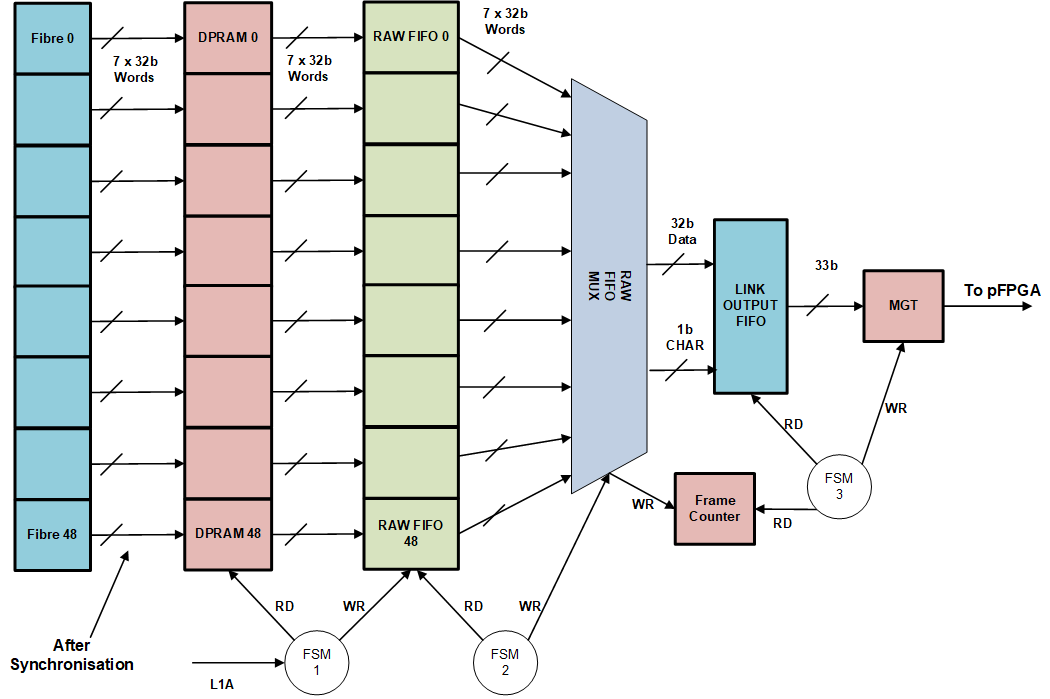
There are 40 ECAL and 9 HCAL input fibres.
Different RAW event are generated depending on buffer levels and control settings:
Sequence of Buffers occupancy levels:
Under Safe Mode operation if the occupancy of TTC FIFO or Link Output FIFO, reaches its FULL occupancy level, then the system synchronisation is lost.
The GEN_CHANNEL loop, generates 49 copies of the RAW data readout blocks within it,these are:
The output of RAW Readout is: 32-bit data word 1-bit data is CHAR 1-bit valid which is the write enable to Link Output FIFO
Header Word:
Header Word 2:
Fibre Trailer Word:
Trailer Word 1:
Trailer Word 2:
Trailer Word 3:
CHAR constants are defined in data_type_pkg.vhd for reference only
Definition at line 214 of file RAW_data_rdout.vhd.
 1.9.1
1.9.1