RAW Calorimeter Data Readout Logic for process FPGA.
This module received synchronised 224-b Calorimeter RAW data and its associated 3-b error flags, and produces writes the data as 7 x 32-b words into dual port scrolling memory.
Upon receiving L1A signals, it produces RAW events of 32-b words with Headr, Trailer and error flags for transmission to control FPGA.
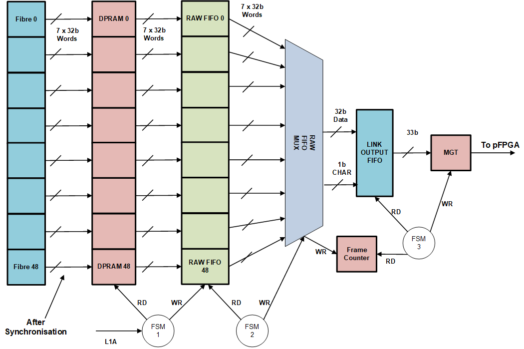
RAW Readout Logic Block Diagram
There are 40 ECAL and 9 HCAL input fibres.
Different RAW event are generated depending on buffer levels and control settings:
- Normal operation when only fibres with error flags set, are assembled into the RAW Event.
- It takes 598 ticks of 280MHz clock to create one event as the FSM must read data for every fibre.
- Normal operation when there are no errors on any fibre.
- In this case, the RAW Event consists of two header words, two error flag payload registers and one trailer word.
- This RAW event takes 15 ticks of 280MHz clock to create as the fibre data is discarded.
- Read_All mode and TTC_Privilege Mode at very low L1A rates.
- In this case the data for every fibre is assembled into RAW event regardless of error status of the links.
- It takes 598 ticks of 280MHz clock to create one event as the FSM must read data for every fibre.
- Safe Mode operation when the buffer levels reach a programmable level.
- In this case, the RAW Event consists of two header words and one trailer word.
- It takes 11 ticks of 280MHz clock to create one event as the RAW data from all fibres are discarded.
Sequence of Buffers occupancy levels:
- When the Ready signal from Control FPGA is removed, complete RAW Events are stored in RAW Link Output FIFO.
- When the occupancy of RAW Link Output FIFO reaches its pFULL occupancy level, then the construction of RAW Events are paused.
- Enough headroom must be assigned in Link Output FIFO to be able to store RAW Events under Safe Mode operation.
- At this point, fibre data are still transferred from Circular DPRAM into de-randomisation RAW Data FIFO.
- When the occupancy of de-randomisation RAW Data FIFO reaches its pFULL occupancy level, no more data is written to this FIFO, and a Safe Mode Flag is set which is stored in TTC FIFO with L1A_ID and BCN.
- A BUSY request must be sent to HUB/ROD to reduce L1A rates at this time.
- At this stage, TTC FIFO and Error Flag FIFO continue to operate and store the L1A_ID, BCN and Error Status of MGT Fibres.
- When the occupancy of TTC FIFO reaches its pFULL occupancy level, the FSM enters the Safe Mode Operation.
- In Safe Mode, all buffers, except RAW Link Output FIFO, are flushed, and very small RAW Events are generated and stored in Link Output FIFO.
Under Safe Mode operation if the occupancy of TTC FIFO or Link Output FIFO, reaches its FULL occupancy level, then the system synchronisation is lost.
The GEN_CHANNEL loop, generates 49 copies of the RAW data readout blocks within it,these are:
- PISO unit - to convert data from 224b to 7 x 32b words
- Dual Port RAM - scrolling memory to store data on every bunch crossing:
- This is circular Dual Port RAM. It stores 7x32b words per Bunch number.
- The DPRAM is 36b wide, and bits 35 to 32 are used to store the 4b error flags for the corresponding MGT Channel.
- The Read and Write address have the correct offset in order to read the actual RAW data associated with the BCN at the time of arrival of L1A.
- Derandomisation FIFO: to store the correct data word upon receiving an L1A:
- This is Derandomisation FIFO. It stores 7x32b words per L1A, which are read out of Circular memory.
- The FIFO is 36b wide, bits 35:32 are used to store the 4b error flags for the corresponding MGT Channel.
The output of RAW Readout is: 32-bit data word 1-bit data is CHAR 1-bit valid which is the write enable to Link Output FIFO
Header Word:
- RAW_out_i(31:20) = ZERO
- RAW_out_i(19:8) = Local (internal) BCN
- RAW_out_i(7:0) = ch_sop2 = X"7C"
Header Word 2:
- RAW_out_i(31:24) = Extended L1_ID
- RAW_out_i(23:0) = Level 1 ID
Fibre Trailer Word:
- RAW_out_i(31:28) = link error (4b = mgt_disable + input_crc + input_disparity + not_in_table)
- RAW_out_i(27:10) = ZERO
- RAW_out_i(9:8) = FPGA Number
- RAW_out_i(7:0) = Optical Link Number
Trailer Word 1:
- RAW_out_i(31:0) = channel_error_map(31 downto 0); – 32b channel error map
Trailer Word 2:
- RAW_out_i(31:28) = link error (4b = read_on_error + input_crc_all + input_disparity_all + not_in_table_all)
- RAW_out_i(27:17) = ZERO
- RAW_out_i(16:0) = channel_error_map(48 downto 32); – 17b channel error map
Trailer Word 3:
- RAW_out_i(31) = safe_mode_i
- RAW_out_i(30:20) = ZERO
- RAW_out_i(19:8) = RAW Payload Counter
- RAW_out_i(7:0) = ch_eop = X"DC"
CHAR constants are defined in data_type_pkg.vhd for reference only
- constant ch_idle : std_logic_vector(7 downto 0) := X"BC" ; – idle char is K28.5
- constant ch_sop1 : std_logic_vector(7 downto 0) := X"3C" ; – TOB/XTOB star of packet char is K28.1
- constant ch_sop2 : std_logic_vector(7 downto 0) := X"7C" ; – CALO DATA start of packet char is K28.3
- constant ch_eop : std_logic_vector(7 downto 0) := X"DC" ; – end of packet char is K28.6
- constant slice_end : std_logic_vector(7 downto 0) := X"5C" ; – end of TOB slice char is K28.2
- constant tx_pause : std_logic_vector(7 downto 0) := X"1C" ; – Tx Data pause is K28.0
- Author
- Saeed Taghavi
Definition in file RAW_data_rdout.vhd.

 1.9.1
1.9.1