Merged Sorted TOB and Local XTOB Readout Logic for process FPGA.
This module received Merged Sorted TOB and Local XTOB data and produces events of 32b words for transmission to control FPGA
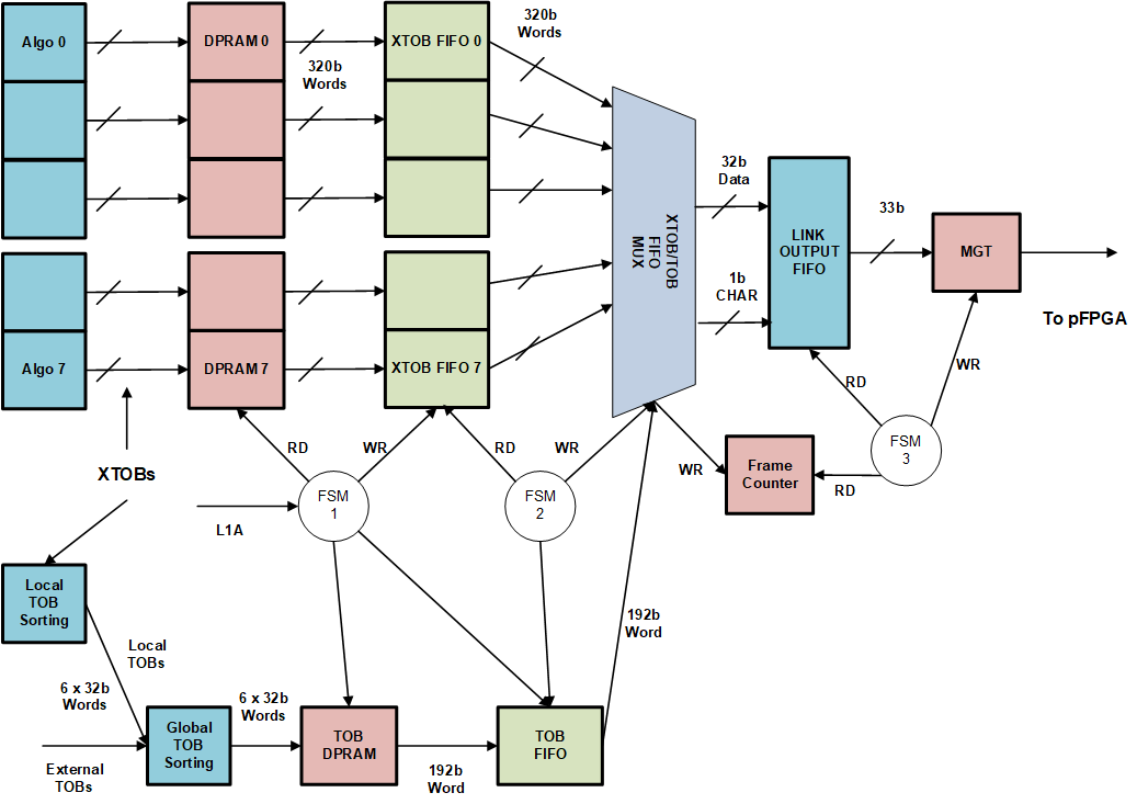
Global Sorted TOBs and Local XTOB Readout Logic Block Diagram
This module is only instanstiated for Process FPGA 1 and 2, and is disabled for Process FPGA 3 and 4.
Different TOB/XTOB data event are generated depending on FPGA Number, buffer levels and control settings.
The Merging FPGAs generate TOB/XTOB data events which consist of maximum 20 tau XTOBs, 20 e/g XTOBs and up to 6 TOBs.
The Non-Merging FPGAs generate XTOB data events which consist of maximum 20 tau XTOBs, 20 e/g XTOBs and do not include Merged TOBs.
- Process FPGA 1 is a merging FPGAs, receive Merged e/g TOBs from the other 3 FPGA. Process FPGA 1 creates an event consisting of locally generated e/g and tau XTOBs, together with Merged e/g TOBs..
- Process FPGA 2 is a merging FPGAs, receive Merged tau TOBs from the other 3 FPGA. Process FPGA 2 creates an event consisting of locally generated e/g and tau XTOBs, together with Merged tau TOBs..
- Process FPGA 3 and 4 are non-merging FPGAs, so do not receive any TOB data from other FPGAs. Process FPGA 3 and 4 create event consisting of locally generated e/g and tau XTOBs, but do not include and Merged TOBs..
- Readout operation for Process FPGAs 1 & 2, create Events which consists of only Valid XTOB/TOBs.
- TOB & XTOB Event in Normal Operation:
- Read 1 Slice - Takes 179 ticks of 280MHz clock to create one TOB & XTOB Event with 1 Slice Readout.
- TOB & XTOB Event in Normal Operation:
- Read 2 Slice - Takes 352 ticks of 280MHz clock to create one TOB & XTOB Event with 2 Slice Readout.
- TOB & XTOB Event in Normal Operation:
- Read 3 Slice - Takes 524 ticks of 280MHz clock to create one TOB & XTOB Event with 3 Slice Readout.
- TOB & XTOB Event in Normal Operation:
- Read 4 Slice - Takes 697 ticks of 280MHz clock to create one TOB & XTOB Event with 4 Slice Readout.
- TOB & XTOB Event in SAFE Mode Operation:
- Read 0 Slices - Takes 8 ticks of 280MHz clock to create one SAFE Mode TOB & XTOB Event.
- Readout operation for Process FPGAs 3 & 4, create Events which consists of only Valid e/g and tau XTOBs..
- XTOB Event in Normal Operation: Read 1 Slice - Takes 171 ticks of 280MHz clock to create one XTOB Event with 1 Slice Readout.
- XTOB Event in Normal Operation: Read 2 Slice - Takes 344 ticks of 280MHz clock to create one XTOB Event with 2 Slice Readout.
- XTOB Event in Normal Operation: Read 3 Slice - Takes 516 ticks of 280MHz clock to create one XTOB Event with 3 Slice Readout.
- XTOB Event in Normal Operation: Read 4 Slice - Takes 691 ticks of 280MHz clock to create one XTOB Event with 4 Slice Readout.
- XTOB Event in SAFE Mode Operation: Read 0 Slice - Takes 8 ticks of 280MHz clock to create one SAFE Mode XTOB Event.
Sequence of Buffers occupancy levels:
- When the Ready signal from Control FPGA is removed, complete TOB/XTOB Events are stored in TOB/XTOB Link Output FIFO.
- When the occupancy of TOB Link Output FIFO reaches its prog FULL occupancy level, then the construction of TOB/XTOB Events are paused.
- Enough headroom must be assigned in Link Output FIFO to be able to store TOB/XTOB Events under Safe Mode operation.
- At this point, TOB/XTOB data are still transferred from Circular DPRAM into de-randomisation TOB/XTOB Data FIFO.
- When the occupancy of de-randomisation TOB/XTOB Data FIFO or TTC FIFO reaches its prog FULL occupancy level,
- A Safe Mode Flag is set which is used to create Safe Mode TOB/XTOB events and empty the TOB/XTOB Data FIFO & TTC FIFO.
- These Safe Mode events consists of 2 Header words, and one Trailer word.
- The payload consists of two words, a ZERO word together with a sub-trailer word for the slice.
- Multi-slice readout contains a number of these double words, equal to the number of slices to be readout.
- A BUSY request must be sent to HUB/ROD to reduce L1A rates at this time.
- In Safe Mode, all buffers, except TOB/XTOB Link Output FIFO, are flushed, and very small TOB/XTOB Events are generated and stored in Link Output FIFO.
Under Safe Mode operation if the occupancy of TTC FIFO or TOB/XTOB Data FIFO, reaches its FULL occupancy level, then the system synchronisation is lost.
The output of TOB Readout is:
- 32-bit data word
- 1-bit data is CHAR
- 1-bit valid which is the write enable to Link Output FIFO
Header Word 1:
- TOBs_out_i(31:24) = TOB BCN
- TOBs_out_i(23:20) = XTOB BCN
- TOBs_out_i(19:8) = Local (internal) BCN
- TOBs_out_i(7:0) = ch_sop = X"3C" (K28.1)
Header Word 2:
- TOBs_out_i(31:24) = Extended L1_ID
- TOBs_out_i(23:0) = Level 1 ID
Trailer Word 1: Slice Trailer
- TOBs_out_i(31) = ZERO
- TOBs_out_i(30) = link_err_flg_in_i
- TOBs_out_i(29:28) = FPGA_mapping
- TOBs_out_i(27) = safe mode
- TOBs_out_i(26:24) = slice number transmitted
- TOBs_out_i(23:18) = XTOB counter tau
- TOBs_out_i(17:12) = XTOB counter e/g
- TOBs_out_i(11:9) = TOB counter
- TOBs_out_i(8) = TOB type in
- TOBs_out_i(7:0) = slice_end = X"5C" (K28.2)
Trailer Word 2: Event Trailer
- TOBs_out_i(31) = safe mode
- TOBs_out_i(30:27) = ZERO
- TOBs_out_i(26:24) = DPR_locations_to_rd (number of slices to read)
- TOBs_out_i(23:20) = trigger slice number
- TOBs_out_i(19:8) = TOB payload counter
- TOBs_out_i(7:0) = ch_eop = X"DC" (K28.6)
CHAR constants are defined in data_type_pkg.vhd
- for reference only
- constant ch_idle : std_logic_vector(7 downto 0) := X"BC" ; – idle char is K28.5
- constant ch_sop1 : std_logic_vector(7 downto 0) := X"3C" ; – TOB/XTOB star of packet char is K28.1
- constant ch_sop2 : std_logic_vector(7 downto 0) := X"7C" ; – CALO DATA start of packet char is K28.3
- constant ch_eop : std_logic_vector(7 downto 0) := X"DC" ; – end of packet char is K28.6
- constant slice_end : std_logic_vector(7 downto 0) := X"5C" ; – end of TOB slice char is K28.2
- constant tx_pause : std_logic_vector(7 downto 0) := X"1C" ; – Tx Data pause is K28.0
TRIGGER SLICE:
- identifies the slice number on L1A, as a number between 0 to 4
- TOB packet header word gets TOB/XTOB BCN from TOB/XTOB data, but internal BCN from L1A_TOB FIFO
- L1A_TOB BCN is always the BCN on L1A, but TOB/XTOB BCN changes depending on Trigger Slice value
07/03/2024 Due to intermitent read error of L1_ID, and further investigations, we found that the input to L1_ID & BNCN FIFO has crossed clock domain from 40MHz to 280MHz. To rule out this may be the cause of error, it was decided to remove read_on_err_in signal from the slice trailer and set it to ZERO.
- Author
- Saeed Taghavi
Definition in file TOBs_rdout.vhd.

 1.9.1
1.9.1