 |
eFEX firmware
1.7.3
ATLAS l1-calo - electron and tau feature extraction firmware for eFEX boards
|
Back to eFEX documentation
|
eFEX firmware
1.7.3
ATLAS l1-calo - electron and tau feature extraction firmware for eFEX boards
|
Merged Sorted TOB and Local XTOB Readout Logic for process FPGA. More...
Processes | |
| U10_dec_frm_cntr | ( TOB_TXOUTCLK ) |
| U14_stop_tob_wr | ( TOB_TXOUTCLK ) |
Signals | |
| RST_i | STD_LOGIC |
| TOB_FIFO_sw_rst_i | STD_LOGIC |
| clk_in_280M_i | STD_LOGIC |
| rdout_T_TOB_209b_i | STD_LOGIC_VECTOR ( 208 downto 0 ) |
| T_TOB_full_i | STD_LOGIC |
| T_TOB_empty_i | STD_LOGIC |
| T_TOB_valid_i | STD_LOGIC |
| T_TOB_prog_full_i | STD_LOGIC |
| T_TOB_FIFO_data_count_i | STD_LOGIC_VECTOR ( 8 downto 0 ) |
| XTOB_eg_FIFO_rd_data_count_i | STD_LOGIC_VECTOR ( 8 downto 0 ) |
| tob_data_mgt_fsm_i | STD_LOGIC_VECTOR ( 7 downto 0 ) |
| tob_data_mux_fsm_i | STD_LOGIC_VECTOR ( 7 downto 0 ) |
| tob_data_dpram_fsm_i | STD_LOGIC_VECTOR ( 7 downto 0 ) |
| xtob_eg_data_dpram_fsm_i | STD_LOGIC_VECTOR ( 7 downto 0 ) |
| xtob_tau_data_dpram_fsm_i | STD_LOGIC_VECTOR ( 7 downto 0 ) |
| DPR_XTOBs_eg_in_i | array_8_of_252b |
| DPR_XTOBs_eg_out_i | array_8_of_252b |
| DPR_XTOBs_tau_in_i | array_8_of_252b |
| DPR_XTOBs_tau_out_i | array_8_of_252b |
| TOB_ready_i | std_logic |
| Control FPGA Ready signal internal. | |
| L1A_rd_en_i | std_logic |
| pre_ld_wr_addr_TOB_i | STD_LOGIC_VECTOR ( 8 downto 0 ) |
| DPR_locations_to_rd_i | STD_LOGIC_VECTOR ( 2 downto 0 ) |
| FIFO_rd_en_i | std_logic := ' 0 ' |
| rdout_XTOB_eg_i | array_8_of_252b |
| rdout_XTOB_tau_i | array_8_of_252b |
| valid_XTOBs_eg_i | STD_LOGIC |
| valid_XTOBs_tau_i | STD_LOGIC |
| frame_cntr_en_i | std_logic |
| frame_cntr_en_ii | std_logic |
| pre_ld_wr_addr_XTOB_eg_i | STD_LOGIC_VECTOR ( 8 downto 0 ) |
| pre_ld_wr_addr_XTOB_tau_i | STD_LOGIC_VECTOR ( 8 downto 0 ) |
| XTOB_eg_full_i | std_logic |
| XTOB_eg_empty_i | std_logic |
| XTOB_eg_prog_full_i | std_logic |
| XTOB_tau_full_i | std_logic |
| XTOB_tau_empty_i | std_logic |
| XTOB_tau_prog_full_i | std_logic |
| TOB_empty_flag_i | std_logic |
| TOB_pfull_flag_i | std_logic |
| TOB_out_valid_i | STD_LOGIC |
| TOB_out_is_char_i | STD_LOGIC |
| TOBs_out_i | STD_LOGIC_VECTOR ( 31 downto 0 ) |
| FIFO_TOBs_in_i | STD_LOGIC_VECTOR ( 32 downto 0 ) |
| Link_output_FIFO_TOBs_out_i | STD_LOGIC_VECTOR ( 32 downto 0 ) |
| TOB_out_to_MGT_i | STD_LOGIC_VECTOR ( 31 downto 0 ) |
| TOB_out_to_MGT_1dly | STD_LOGIC_VECTOR ( 31 downto 0 ) |
| TOB_data_out_MGT_i | STD_LOGIC_VECTOR ( 31 downto 0 ) |
| Link_output_FIFO_rd_en_i | STD_LOGIC |
| TOB_out_to_MGT_is_char_i | STD_LOGIC |
| TOB_out_to_MGT_is_char_1dly | STD_LOGIC |
| Link_output_FIFO_TOB_valid_i | STD_LOGIC |
| T_TOB_out_valid_i | STD_LOGIC |
| T_TOB_out_valid_1dly | STD_LOGIC |
| TOB_out_char_MGT_i | STD_LOGIC |
| Link_output_FIFO_full | std_logic |
| Link_output_FIFO_empty | std_logic |
| Link_output_FIFO_prog_full | std_logic |
| Link_output_FIFO_prog_empty | std_logic |
| TOB_data_FIFO_flags_i | STD_LOGIC_VECTOR ( 31 downto 0 ) |
| reg1 | std_logic := ' 0 ' |
| reg2 | std_logic := ' 0 ' |
| frame_cntr_dec_en_i | std_logic |
| frame_counter_dec_en_i | std_logic := ' 0 ' |
| frame_count_i | STD_LOGIC_VECTOR ( 11 downto 0 ) |
| TOB_safe_mode_i | std_logic |
| tob_busy_assert_i | std_logic |
| SPY_TOB_mem_wr_addr_i | STD_LOGIC_VECTOR ( 10 downto 0 ) |
| SPY_TOB_mem_wr_addr_en_i | STD_LOGIC |
| SPY_FIFO_TOB_in_i | STD_LOGIC_VECTOR ( 35 downto 0 ) |
| SPY_TOB_mem_rd_data_i | STD_LOGIC_VECTOR ( 35 downto 0 ) |
| enable_tob_spy_mem_wr | std_logic |
| tst_fsm_cntr_i | STD_LOGIC_VECTOR ( 31 downto 0 ) |
| q1_int | STD_LOGIC_VECTOR ( 31 downto 0 ) |
| BCN_FIFO_rd_en_i | std_logic |
| BCN_FIFO_full_i | std_logic |
| BCN_FIFO_empty_i | std_logic |
| BCN_FIFO_valid_i | std_logic |
| BCN_FIFO_prog_full_i | std_logic |
| BCN_FIFO_Data_in_i | STD_LOGIC_VECTOR ( 46 downto 0 ) |
| BCN_FIFO_Data_in_1dly | STD_LOGIC_VECTOR ( 46 downto 0 ) |
| BCN_FIFO_Data_out_i | STD_LOGIC_VECTOR ( 46 downto 0 ) |
| FIFO_BCN_in_i | STD_LOGIC_VECTOR ( 11 downto 0 ) |
| FIFO_L1A_ID_i | STD_LOGIC_VECTOR ( 23 downto 0 ) |
| FIFO_L1A_ID_EXT_i | STD_LOGIC_VECTOR ( 7 downto 0 ) |
| LO_FIFO_rd_data_count_i | STD_LOGIC_VECTOR ( 12 downto 0 ) |
| LO_FIFO_wr_data_count_i | STD_LOGIC_VECTOR ( 12 downto 0 ) |
| busy_tob_i | std_logic |
| L1A_in_1dly | std_logic |
| L1A_in_2dly | std_logic |
| L1A_in_3dly | std_logic |
| read_on_err_i | std_logic |
| sync_280m_i | std_logic |
| SPY_mem_wr_addr_tc_i | std_logic |
Attributes | |
| TIG | string |
| TIG | signal is " true " |
| keep | string |
| max_fanout | integer |
| keep | signal is " true " |
| max_fanout | signal is 40 |
| max_fanout | signal is 25 |
Instantiations | |
| u1_gen_sync_280 | gen_sync_280M <Entity gen_sync_280M> |
| u0_fdce_xoff | fdce |
| u0_busy_flag_fsm | busy_flag_fsm <Entity busy_flag_fsm> |
| u0_fifo_bcn_l1a | fifo_47b_512 |
| u1_tobs_sorting | T_TOBs_sorting <Entity T_TOBs_sorting> |
| u2_xtobs_eg_sorting | XTOBs_sorting <Entity XTOBs_sorting> |
| u3_xtobs_tau_sorting | XTOBs_sorting <Entity XTOBs_sorting> |
| u6_rd_mux_fsm | fsm_TOBs_to_muxPISO <Entity fsm_TOBs_to_muxPISO> |
| u7_link_output_fifo | fifo_33b_8192 |
| u8_tob_link_output_fifo_fsm | FIFO_to_MGT_TOB_FSM <Entity FIFO_to_MGT_TOB_FSM> |
| u9_clk_closs_pulse | clk_closs_pulse_fsm <Entity clk_closs_pulse_fsm> |
| u9_frame_counter | cntr_up_dn_generic <Entity cntr_up_dn_generic> |
| u12_tob_spy_mem | ipbus_dpram |
| u13_spy_mem_wr_addr | cntr_generic <Entity cntr_generic> |
Merged Sorted TOB and Local XTOB Readout Logic for process FPGA.
This module received Merged Sorted TOB and Local XTOB data and produces events of 32b words for transmission to control FPGA
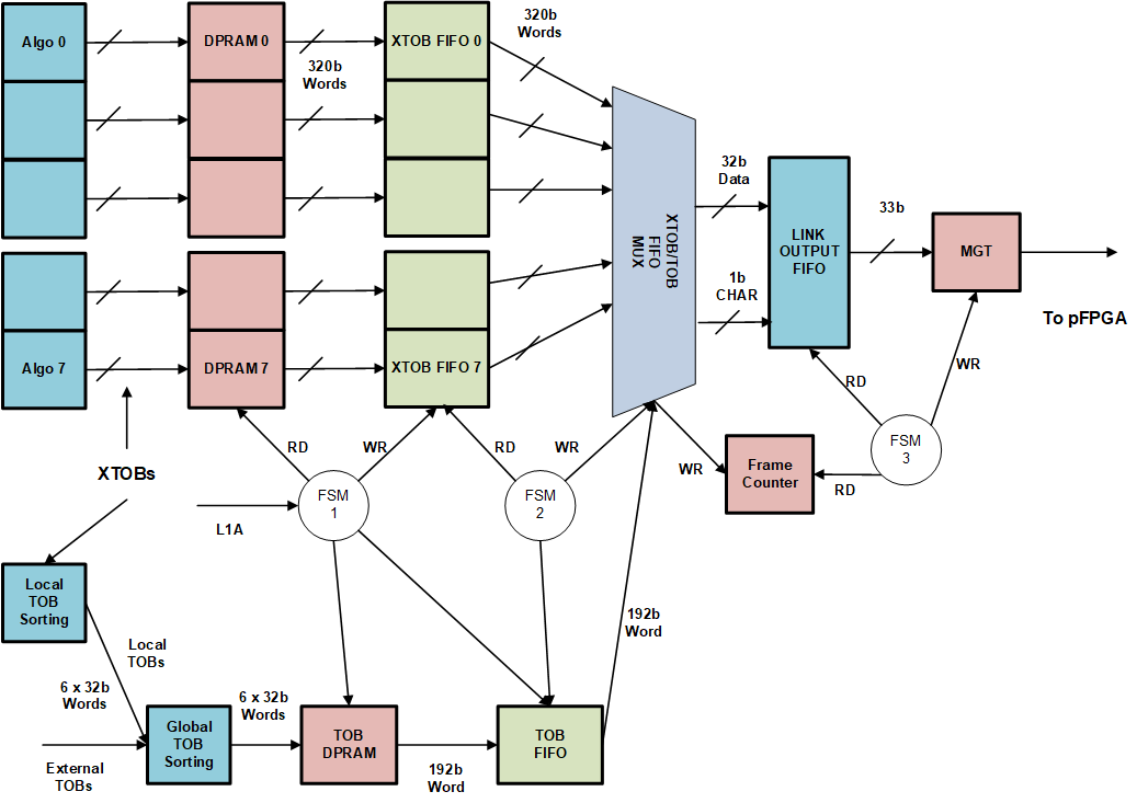
This module is only instanstiated for Process FPGA 1 and 2, and is disabled for Process FPGA 3 and 4.
Different TOB/XTOB data event are generated depending on FPGA Number, buffer levels and control settings.
The Merging FPGAs generate TOB/XTOB data events which consist of maximum 20 tau XTOBs, 20 e/g XTOBs and up to 6 TOBs.
The Non-Merging FPGAs generate XTOB data events which consist of maximum 20 tau XTOBs, 20 e/g XTOBs and do not include Merged TOBs.
Sequence of Buffers occupancy levels:
Under Safe Mode operation if the occupancy of TTC FIFO or TOB/XTOB Data FIFO, reaches its FULL occupancy level, then the system synchronisation is lost.
The output of TOB Readout is:
Header Word 1:
Header Word 2:
Trailer Word 1: Slice Trailer
Trailer Word 2: Event Trailer
CHAR constants are defined in data_type_pkg.vhd
TRIGGER SLICE:
07/03/2024 Due to intermitent read error of L1_ID, and further investigations, we found that the input to L1_ID & BNCN FIFO has crossed clock domain from 40MHz to 280MHz. To rule out this may be the cause of error, it was decided to remove read_on_err_in signal from the slice trailer and set it to ZERO.
Definition at line 283 of file TOBs_rdout.vhd.
 1.9.1
1.9.1