 |
eFEX firmware
1.7.3
ATLAS l1-calo - electron and tau feature extraction firmware for eFEX boards
|
Back to eFEX documentation
|
eFEX firmware
1.7.3
ATLAS l1-calo - electron and tau feature extraction firmware for eFEX boards
|
Top Level of Readout Logic for process FPGA. More...
Go to the source code of this file.
Entities | |
| Readout_logic_top | entity |
| Top Level of Readout Logic for process FPGA. More... | |
| Behavioral | architecture |
| Top Level of Readout Logic for process FPGA. More... | |
Top Level of Readout Logic for process FPGA.
This is the top module of the Readout Logic The inputs are:
The Readout output is two streams of 32b data and consists of:
Two streams of 32b data is fed to two MGTs through Link Output FIFOs for tranfer to Control FPGA
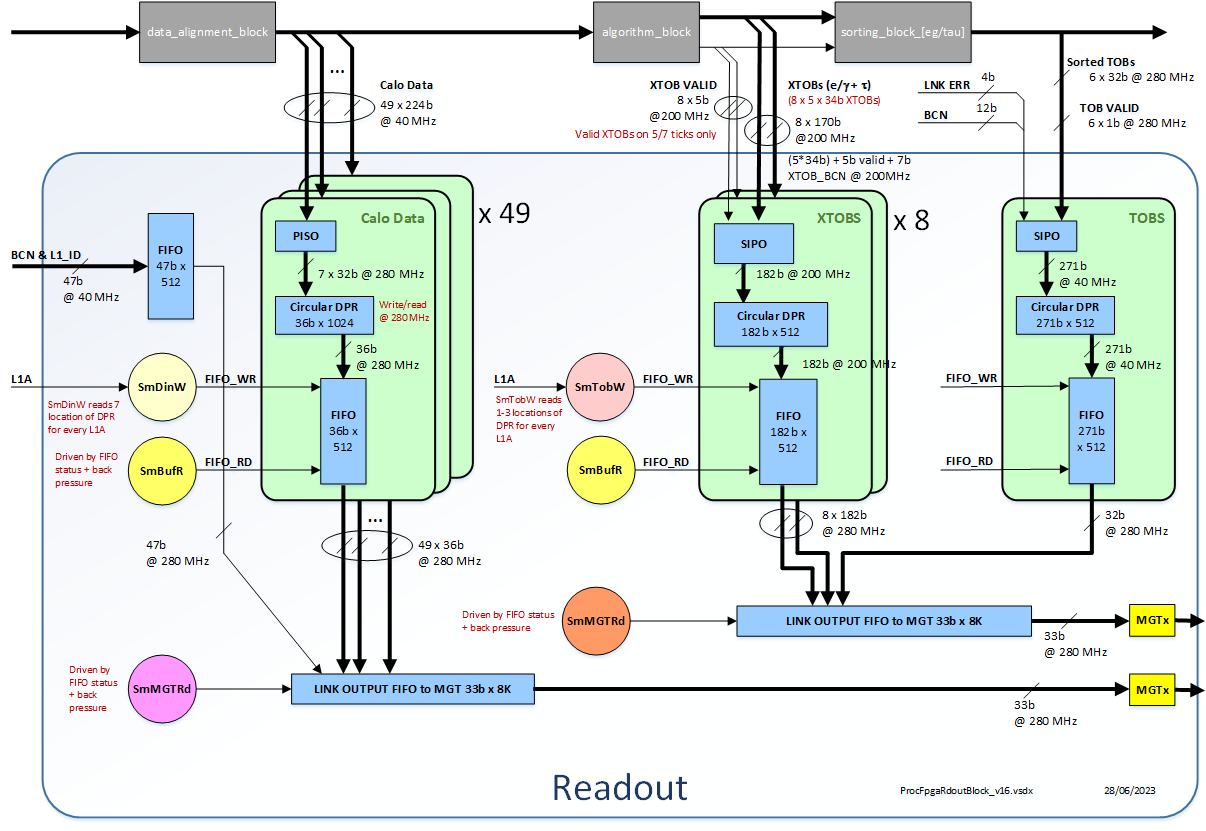
This block consists of four submodules: Submodule 1 : TOBs_Readout Submodule 2 : RAW_data_Readout Submodule 3 : readout_ipb_slave Submodule 4 : L1A counter
TOBs_Readout Module is responsible for reading the merged sorted TOBs and local XTOBS from outputs of Algo Block, and creating a full events, storing only valid TOBs and XTOBs.
RAW_data_Readout Module is responsible for reading the RAW calorimeter data from synchronisation block.
Tidemark register are implemented for following FIFOs: TOB Readout: TOB FIFO, XTOB FIFO, L/O FIFO, BCN/LI_ID FIFO As the fill levels for TOBs, XTOBs and BCN/LI_ID FIFOs are identical, the Tidemark is implemented for XTOB e/g FIFO and shared for others 32-bit register now contains: bit(31:16) Tidemark fill value bit(15:0) Instantaneous fill value
RAW Readout: RAW input FIFO, L/O FIFO, BCN/LI_ID FIFO As the fill levels for for all 49 input data FIFOs are identical, the Tidemark is implemented for Link 0 only 32-bit register now contains: bit(31:16) Tidemark fill value bit(15:0) Instantaneous fill value
Tidemark registers are all cleared by Busy counter Reset pulse
Readout_ipb_slave Module is responsible for communication with IPBus. All registers in RAW and TOB blocks are accessed trough this module.
TOB Busy Counter is responsible for counting the Number of TOB Readout BUSY assertions. Cleared by Busy counter Reset pulse
RAW Busy Counter is responsible for counting the Number of RAW Readout BUSY assertions. Cleared by Busy counter Reset pulse
ECR Debug Counter is responsible for counting the Number ECR assertions. Cleared by ECR Debug Reset pulse
L1A Debug Counter is responsible for counting the Number EL1A assertions. Cleared by L1A Debug Reset pulse
TOB Busy Duration Counter is responsible for counting Duration that TOB Readout BUSY is asserted. Cleared by Busy counter Reset pulse
RAW Busy Duration Counter is responsible for counting Duration that RAW Readout BUSY is asserted. Cleared by Busy counter Reset pulse
Real Time Counter is responsible for counting the Number of 40MHz ticks. Cleared by Busy counter Reset pulse
TOB Double Word Counter is responsible for counting the Number identical double words transmitted to control FPGA.. Cleared by SPY RAM write address Reset pulse
L1A_cntr Module is responsible for generating L1A_ID. The first event has L1A_ID of ZERO. Cleared by L1A ID Reset pulse.
Definition in file Readout_logic_top.vhd.
 1.9.1
1.9.1