 |
eFEX firmware
1.7.3
ATLAS l1-calo - electron and tau feature extraction firmware for eFEX boards
|
Back to eFEX documentation
|
eFEX firmware
1.7.3
ATLAS l1-calo - electron and tau feature extraction firmware for eFEX boards
|
Data path block. More...
Components | |
| ila_inputRam | |
Signals | |
| algo_in | AlgoInput |
| eg_Sync | std_logic |
| eg_XSync | std_logic |
| tau_XSync | std_logic |
| eg_XValid | std_logic_vector ( OUTPUT_TOBS- 1 downto 0 ) |
| tau_XValid | std_logic_vector ( OUTPUT_TOBS- 1 downto 0 ) |
| eg_TOB | AlgoOutput |
| tau_TOB | AlgoOutput |
| eg_XTOB | AlgoXOutput |
| tau_XTOB | AlgoXOutput |
| eFEXPosition | std_logic_vector ( 31 downto 0 ) |
| Geographic position of eFEX Module, for the mapping logic. | |
| mgt_data_int | mgt_data_in |
| ram_data_int | ram_data_in |
| sorted_TOB_BCN_i | std_logic_vector ( 11 downto 0 ) |
| XTOB_BCN_i | std_logic_vector ( 11 downto 0 ) |
| TOB_BCN_i | std_logic_vector ( 11 downto 0 ) |
| probe0 | STD_LOGIC_VECTOR ( 19 DOWNTO 0 ) |
| bcn_cntr_i | std_logic_vector ( 11 downto 0 ) |
Attributes | |
| keep | string |
| max_fanout | integer |
| keep | signal is " true " |
| max_fanout | signal is 30 |
Instantiations | |
| data_alignment_block | data_alignment <Entity data_alignment> |
| algorithm_block | IPBusTopAlgoModule <Entity IPBusTopAlgoModule> |
| sorting_module | IPBusTopSortingModule <Entity IPBusTopSortingModule> |
| tob_bcn_cntr | local_bcn_counter <Entity local_bcn_counter> |
Data path block.
The data path module is a container for three functional modules: data alignment, algorithm, local TOB sorting. This is a block diagram of the data path block:
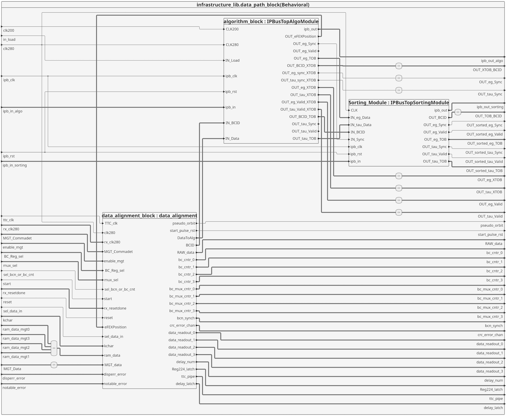
The data coming form the MGTs is provided to the alignment block that decodes them to the algorithm input format.
This decoding is done differently for FPGA U1, U2, U3, U4 depending on the generic FPGA_NUMBER. Data decoding also depends on the eFEX module position that can be set at runtime with an IPbus register called "position" in the algorithm module. The value of this register is fed back from the algorithm to the data alignment module.
XTOBs coming out of the algorithm @200MHz together with the BC number are sent to output ports to be fed to the XTOB readout. Unsorted local TOBs (max 40) are sent from the algorithm to the sorting module.
Sorted tobs (max 7), coming out of the sorting module @280 MHz are sent out of the data path block. These can go either to the merging FPGAs or to the merging module. This block doesn't add any latency and does not contain any process.
Definition at line 151 of file data_path_block.vhd.
 1.9.1
1.9.1